Using external voltage regulators
Contents
Using external voltage regulators
Although the Pro Mini has a built in voltage regulator, its max. load doesn’t match the current draw of the ESP-01. Unfortunately, the max load the internal regulator can handle is not specified. Estimations I’ve read about in forums ranged from 35 mA up to 500 mA. We can safely assume it’s somewhere between 100 mA and 200 mA.
Obviously, we need to add an external regulator to our circuitry. We would be burning off a lot of power if we used the external voltage regulator for the ESP-01 AND the internal one of the Arduino. It would be more efficient if we just use the external one and provide its regulated voltage to both the VCC (3.3v) of the Pro Mini and Vcc of the ESP-01. Lets say we need about 500 mA to cover the load of both module plus safety and future extensions of the circuitry. I tried a few external voltage regulators and I’m happy that I can share my findings with you. During testing, I always used a 6 – 7V output battery setup. For a better understanding of this battery setup, take a look at the battery chapter in this article.
There are basically two types of regultators, linear and switched. Linear regulator usually have an efficiency rate of around 80%, whereas switching regulators can achieve efficiency rates up to 96 %. The potential efficiency rate also depends on the setup and design of the circuitry. During my testing of three different voltage regulators, I was in for a big surprise.
AMS1117- 3.3v Module
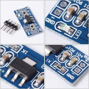 The picture shows a voltage regulator module based on the AMS1117 linear regulator chip. This module has some design flaws, but electrically it’s not that bad. Its form factor doesn’t make it well suited to be put on a breadboard because it will span most of the holes with barely one row left at both ends. It also features a bright red LED, which consumes power we definitely want to save for other purposes (I just cut it in the middle and scratched its leftovers from the module leaving the soldering pads untouched). Take into consideration that the AMS1117 gets really hot if the supplied voltage is high and your circuit draws a lot off current. Since there is no heatsink on the module, the AMS1117 quickly shuts off when it gets too hot.
The module specifies a maximum load of 800 mA with a fixed output voltage of 3.3V. Due to the working principle of a voltage regulator, we need to add its drop out voltage to the voltage it’s designed to supply. In this case the drop out voltage is about 1.2v, so we need to supply at least 4.5v if we want to get a stable 3.3v output from it. From the three voltage regulators I tested this one was second best. I measured a current of 6 mA when the Pro MIni and ESP-01 were put to sleep, which isn’t bad because the ESP-01 and Arduino Pro Mini were still powererd and their LEDs illuminated. We can put this value into better perspective when we see the results from the other modules.
Washati® Mini DC Buck Step-Down Modul (4.75V-23V to 1.0-17V)
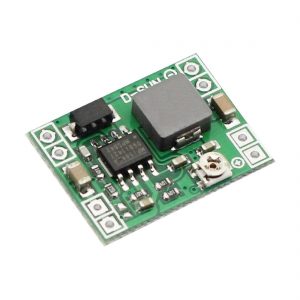 The Washati step-down (buck) voltage regulator module accepts an input voltage which can range from 4.75V – 23V. The module’s output voltage can be adjusted between 1.0 – 17V. It was quite tricky to adjust the output voltage to 3.3V because the potentiometer was highly sensitive. Just touching it could change the output voltage a little bit.
The adjustable output voltage and an average current output of 1.8A don’t come for free. When using this module, my circuit consumed 9,6 mA in power down mode, compared to 6 mA when I tried the AMS1117-based module. Of the three modules I tested, this one obviously had the highest quiescent current (quiescent current is the current drawn by a circuit when it is not amplifying a signal or driving a load).
Pololu 3.3V, 500mA Step-Down Voltage Regulator D24V5F3
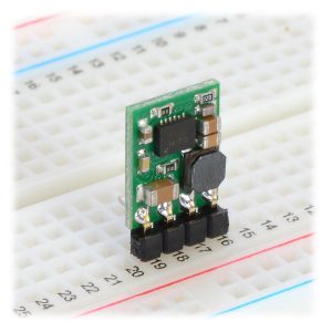 I was totally surprised when I tested the third module. The Pololu step-down voltage regulator is a switching regulator with a very low drop-out voltage (0,25V). Although the smallest of the three regulator modules, it performed best by almost a magnitude. I couldn’t believe my eyes: 1.6 mA was displayed on my multimeter. It has a fixed output voltage of 3.3V and a maximum output current of 500 mA. Switching regulators are more efficient than linear voltage regulators, especially when the difference between the input and output voltage is large. Its low quiescent (no load) current draw of approximately 200 μA makes it well suited for low-power applications that are run from a battery. Last but not least, the SHDN pin can be driven low (under 0.4V) to turn off the output and put the board into a low-power state. There is also a 100 kΩ pull-up resistor between the SHDN pin and VIN.
Although all three regulators are designed for loads of 500 mA and above, it doesn’t mean we are off the hook of a voltage drop. Without going into to much detail, we need to decouple the ESP-01 from our power supply by using capacitors. Such a capacitor is our first line of defense, when it comes to voltage sags. Such a defense line only makes sense if put right in front of the enemy, and that’s the ESP-01. The capacitor must be connected directly or adjacent to its Vcc and ground pins, so it is first in line when the ESP-01 suddenly requires more power than can be delivered in time. A nice sideeffect of the capacitor is that it allows the battery to last longer before causing a brown-out. Remember, the more the battery looses voltage, the more likely its voltage will drop below the circuit’s limit when the ESP-01 gets in action. A capacitor will significantly delay the point of time before the battery’s voltage finally drops below that limit and the Pro Mini starts resetting.
Although the Pololu voltage regulator performed best during my tests, I chose the AMS1117-3.3V based regulator to continue my development. The Pololu came from UK, so it took some time to reach my home in Germany, and I was already using the AMS1117. It was also the most expensive regulator in the set of three, so I didn’t want to risk damaging it.
Now it’s time to spend some thought about the battery we want to use. The higher the input voltage into the regulator, the lower the voltage drop will be when the ESP-01 wakes up. Therefore, putting three AA Alkaline batteries in series will not solve the problem. Four of them will be better. Alkaline batteries have one big disadvantage, though. The voltage of a single AA battery constantly decreases during usage, down to about 1.0 Volt when nearing its depletion. That makes 4.0 Volt and that’s again not enough for the regulator to maintain 3.3V output. Adding another AA battery exceeds the maximum input voltage of the regulator. This sucks.