Power Management - The Final Chapter
Contents
Power Management – The Final Chapter
In the previous chapter we talked about power savings by employing sleep modes of both Arduino Pro Mini and ESP8266-01. We can further reduce AND simplify our circuit by getting rid of unneeded Pro Mini components. Since we don’t use the Pro Mini’s internal regulator nor do we have any use for the power LED, we can as well leave them out of the equation by replacing the Pro Mini by the barbone MCU chip ATmega328p. But that would be too drastical because it would miss the title of this article. If you have a genuine Arduino Pro Mini, there should be a small soldering blob next to the GND and RST pins named SJ1. To isolate the regulator from VCC, remove the solder blob on the top of the board with a sucker or solder wick. To understand its function, the Sparkfun schematic might be helpful.
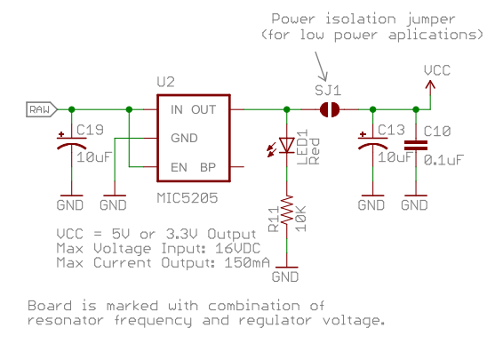
For the full schematic, see this document. In order to save even the smallest amount of current, consider to cut or remove the power LED from the Pro Mini PCB. If you have a chine clonse of the board, it is likely that it doesn’t breakout the SJ1 jumper. If you are no coward and you have such a board and you are serious about power reduction, removing both the power LED and the internal voltage regulator from the Pro Mini PCB might be an option.
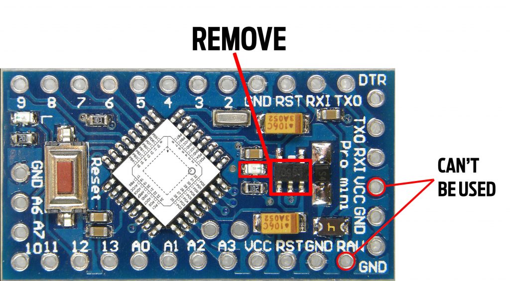
If you remove it, the RAW pin and Vcc from the programming header won’t be usable any more, as depicted in the above picture.