Setting Up the ESP8266-01 Module
Contents
Setting up the ESP8266-01 module
In order to program the ESP-01 module you need a USB RS232 to TTL adapter. Preferably, you have a “USB-zu-ESP8266 Module” which doesn’t need much cabling because you just stick you ESP8266 module in its socket andc that’s it (almost).
Parts list:
- ESP8266-01
- USB-zu-ESP8266 Adapter
- Resistor 5 kOhm
See the resistor on tbe list? It is required to pull down the GPIO0 signal of the ESP8266-01 which switches it into programming mode. Just hang the ends of the resistor in the GND and GPIO0 pin socket …
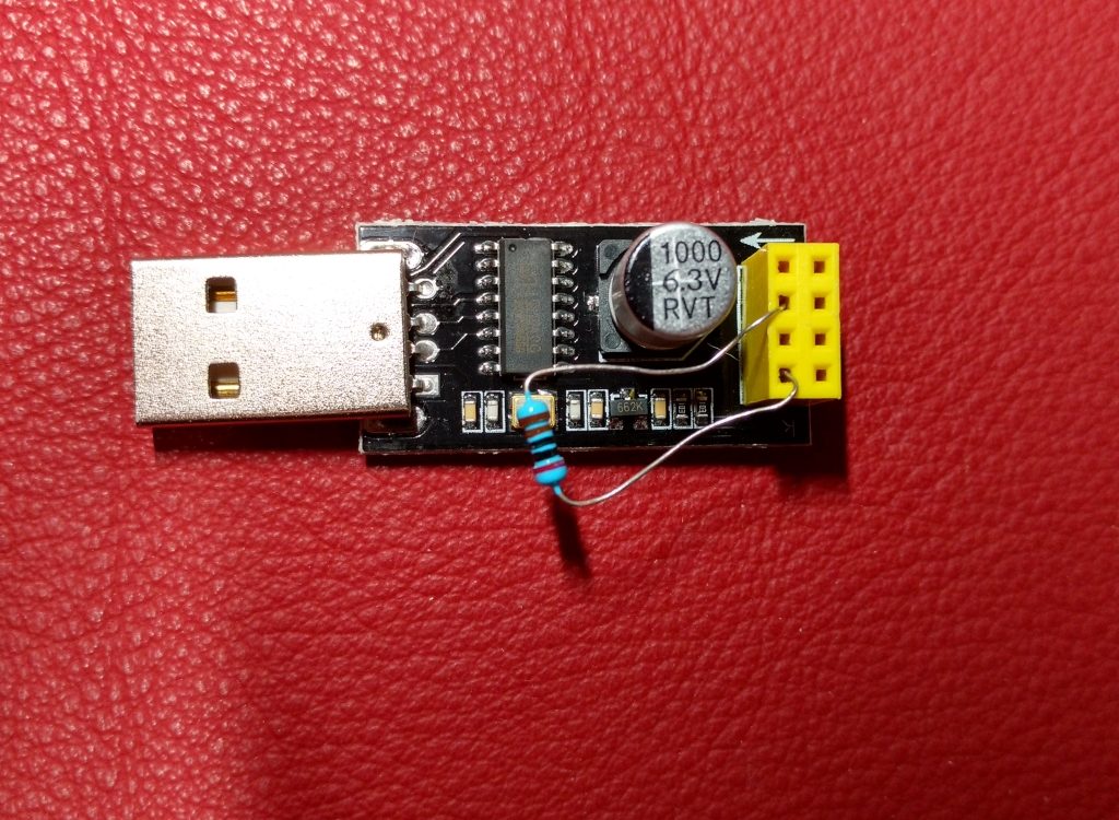
… and press the ESP8266-01 into it.

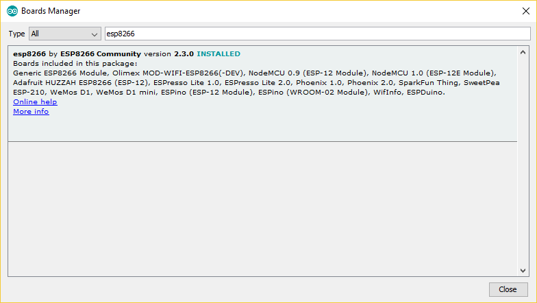
Now it is ready to be programmed. For programming, we use the Arduino IDE. As a prerequisiste, you need to install the EPS8266 board platform by using the “Boards Manager” and look for “ESP8266”. Select the corresponding entry in the list and click on “Install”. Finally, the screen should look like this:
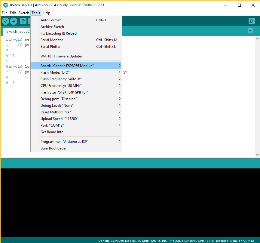
Now stick the adapter with the ESP module attached to it into a USB-port of your workstation. In the “Tools” menu select a new board. Look out for the “Generic ESP8266 Module”. When you selected it, the “Tools”-Menu should look like this (the port could be different):
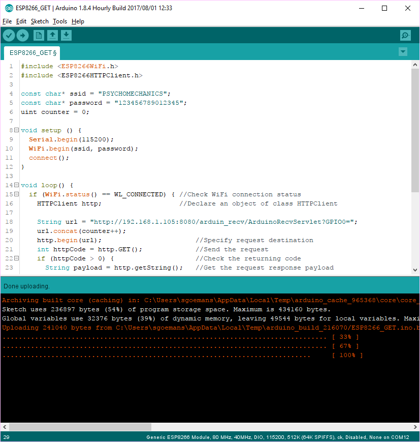
The following code listing simply sends a HTTP query string parameter to a server. The server (Tomcat) is running a servlet which is instantiated as soon as a client hits the servlets corresponding (listening) URL mapping.
#include <ESP8266WiFi.h>
#include <ESP8266HTTPClient.h>

const char* ssid = "PSYCHOMECHANICS";
const char* password = "1234567890abcdefgh";
uint counter = 0;

void setup () {

  Serial.begin(115200);
  WiFi.begin(ssid, password);
  connect();
}

void loop() {
  if (WiFi.status() == WL_CONNECTED) {     //Check WiFi connection status
    HTTPClient http;                       //Declare an object of class HTTPClient

    String url = "http://192.168.1.105:8080/arduin_recv/ArduinoRecvServlet?GPIO0=";
    url.concat(counter++);
    http.begin(url);                       //Specify request destination
    int httpCode = http.GET();             //Send the request
    if (httpCode > 0) {                    //Check the returning code
      String payload = http.getString();   //Get the request response payload
      Serial.println(payload);             //Print the response payload
    }
    http.end();   //Close connection
  } else {
    connect();    //Re-establish connection if lost
  }
  delay(30000);   //Pause for 30 seconds
}

void connect() {
    while (WiFi.status() != WL_CONNECTED) {
    delay(1000);
    Serial.print("Connecting..");
  }
}
Now that is not the most sophisticated piece of code possible for our purpose, but it will do. Pay particular attention to the URL that is generated before connecting with http.begin(url); We must ensure that the server is listening to this exact URL. The server address and port is easy to figure out, but the context path is something beginners often fail to understand. Even if they do, they still have problems finding out which context path the server finally listens to. For now, just keep in mind that the HTTP’s query string in the above code contains a parameter named “GPIO0” and an incrementing integer as its value. In the loop, this value is updated every 30 seconds. After 10 hours, the value should be 1200 (2 per minute x 60 min x 10 hours = 1200).
When you flash the code onto the ESP module, the debug output in the Arduino IDE should look like this:
Now that the code is finally stored on the ESP module, we can disconnect it from the USB adapter and use it independently from it, provided you have a stable 3.3v Voltage at hand. There is one important thing to account for, and that’s the different operation modes of the ESP module. Pulling GPIO0 down to low level puts it into programming mode. For normal operation, the CS_PD signal must be pulled up to high. Otherwise, the module won’t run our code.