Introduction
The Arduino MKR1000 module contains a wealthy lot more SRAM than the Arduino UNO or even MEGA. This, and its 3.3 V base voltage makes it the ideal platform for using it with the Waveshare 1.54 Inch E-Paper Display Panel Module. This article describes how to connect the display module to the MKR1000 and run the vendor’s example program on it. Hooking up the e-paper module with the MKR1000 is particularly interesting when looking at its extremely low power consumption. In a later article I will shed some light on the operation of both modules when using a LiPo battery power source.
Pay particular attention to the “Using the Adafruit_GFX library” paragraph at the end of this article, as it describes the usage of an alternate text/graphics library.
Parts list:
- Arduino MKR1000
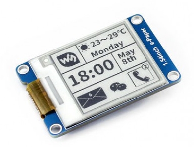
- Waveshare 1.54 Inch E-Paper Display Panel Module Kit 200×200 Resolution 3.3v (Support Partial Refresh)
- Breadboard 400-Points
MKR1000 Pin Layout
The MKR1000 pins we will be using are D4, D5, D6, D7, D8, D9, GND, and 5V. Check the location of these pins:
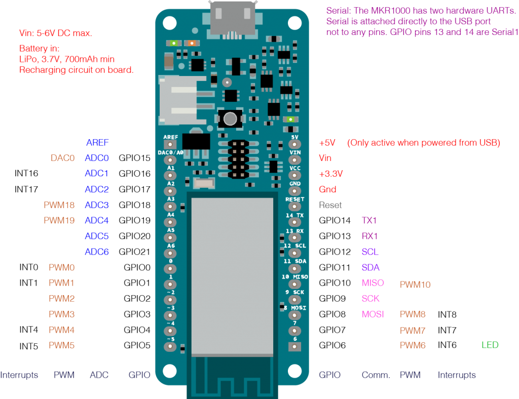
It is important to know that the SPI pins off the MKR1000 differ from the Arduino UNO. As you can see in the above picture, the SPI pins are D8 (MOSI), D9 (SCK), and D10 (MISO). The SPI pins on the UNO are D11 (MOSI), D12 (MISO), and D13 (SCK). The Arduino column in the following table lists the pins for an Arduino UNO. This column corresponds to the Waveshare Wiki page. Because we use the MKR1000 instead, we need to re-map the UNO pins to the MKR1000 pin layout. The two SPI signals SCK and MOSI must be remapped to D9 and D8 for the MKR1000. The remaining signals like CS, DC, RST and BUSY can be freely mapped to the other digital signals of the MKR1000 as you can see in the “MKR1000” column in the table.
|
e-Paper |
Arduino |
MKR1000 |
|
|
3.3V |
3V3 |
Red |
VCC |
|
GND |
GND |
Black |
GND |
|
DIN |
D11 (MOSI) |
Blue |
D8 (MOSI) |
|
CLK |
D13 (SCK) |
Yellow |
D9 (SCK) |
|
CS |
D10 |
Orange |
D4 |
|
DC |
D9 |
Green |
D7 |
|
RST |
D8 |
White |
D6 |
|
BUSY |
D7 |
Violet |
D5 |
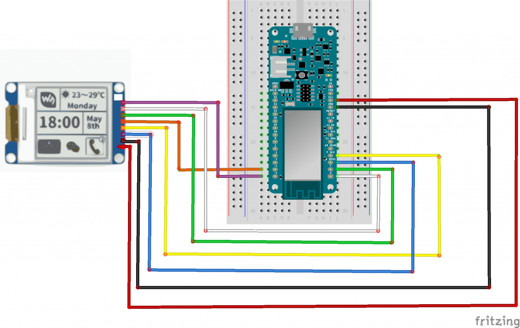
See the re-mapping of the other signals so they don’t collide with the SPI pins of the MKR1000. Well, thats pretty much it, hardwarewise. Take a look at the wiring of the components:
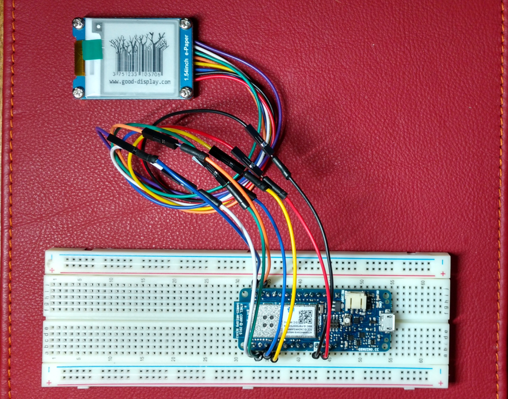
Here my real wiring:
The Demo Sketch
The Waveshare demo sketch string.ino uses the signal definitions from the header file EPD_drive_gpio.h. This file must be modified to reflect our mapping:
#ifndef _EPD_DRIVE_GPIO_H_
#define _EPD_DRIVE_GPIO_H_
#include <SPI.h>

/********************------------------------------------------------------------

Hardware interface

------------------------------------------------------------------------------*/
//GPIO config

#define CS 4
#define EPD_CS_0 digitalWrite(CS,LOW)
#define EPD_CS_1 digitalWrite(CS,HIGH)
#define isEPD_CS digitalRead(CS)

#define RST 6
#define EPD_RST_0 digitalWrite(RST,LOW)
#define EPD_RST_1 digitalWrite(RST,HIGH)
#define isEPD_RST digitalRead(RST)

#define DC 7
#define EPD_DC_0 digitalWrite (DC,LOW)
#define EPD_DC_1 digitalWrite (DC,HIGH)

#define BUSY 5
#define isEPD_BUSY digitalRead(BUSY)
#define EPD_BUSY_LEVEL 0

extern void SPI_Write(unsigned char value);
extern void driver_delay_xms(unsigned long xms);
#endif
Only the four GPIO signals need to be set here. For the remaining two SPI signals SPI.h takes care of the different board’s pin layouts.
Now its time to connect the MKR1000 to your PC via USB. After you selected the correct port and upload the sketch to the MKR1000, its done. My MKR1000 drops its USB connection when the sketch launches, and sometimes when it reconnects it is not recognized by my PC any more. In that case, just disconnect the VCC wire before you upload the sketch and reconnect it after the USB connection is re-established (wait for USB connect sound).
Using the Adafruit_GFX library
The demo sketch from Waveshare contains two simple and small fonts, one 12 pixel and the other 16 pixel. This is definitely not enough for anything but basic function tests. Luckily, the ADafruit_GFX library provides a wealth of
Well, this guy ZinggJM saves us all from frustration and despair, as he developed a wrapper for the Adafruit_GFX library which provides functionality for pixel based displays. It is an E-Paper display library with common base class (a subclass of Adafruit_GFX) and separate IO class for Arduino to have graphics and text rendering. Because of its size, running it on an Arduino UNO is not possible. BUT, it fits quite snuggly in the MKR1000’s 8KB of SRAM. Perhaps the limited 1.54 display size contributes to the small memory requirement.
If you want to test JinggJM’s library, go to https://github.com/ZinggJM/GxEPD. Download the whole package and run the NicePartialUpdateDemo_1.54.ino from the examples folder. I took the required wiring from the lines 64 – 65. Its not a coincidence that the pins match the layout from the previous example 🙂
GxIO_Class io(SPI, 4 /* CS */, 7 /* DC */, 6 /* RST */);
GxEPD_Class display(io, 6 /* RST */, 5 /* BUSY */);
I added a few comments to better visualize which pin wiring is required to run the example. You might notice that the two SPI signals are missing. That is correct because they will be taken automatically from the corresponding MKR1000 platform pin definitions. We just need to make sure that we correctly wire the official SPI pins (like we did in the first example). To make things easier for you, here is the pin mapping table again for use with JinggJM’s library:
|
e-Paper |
MKR1000 |
|
|
3.3V |
Red |
VCC |
|
GND |
Black |
GND |
|
DIN |
Blue |
D8 (MOSI) |
|
CLK |
Yellow |
D9 (SCK) |
|
CS |
Orange |
D4 |
|
DC |
Green |
D7 |
|
RST |
White |
D6 |
|
BUSY |
Violet |
D5 |
Aside of the examples folder only the GxGDEP015OC1 and GxIO folders are required if you stick with the 1.54inch display module.