Introduction
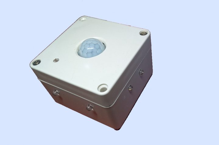
The idea behind a battery powered night light came from my realization that my bedside cabinet was already cluttered by a few electrical appliances, like a lamp, a radio, and a smartphone power adapter, and fumbling around while searching the light switch usually caused something to drop onto the floor. A night light usually requires a power socket, and in my case the socket was behind my nightstand. Aside from the discussion about electromagnetic pollution, of which for sure I already was plenty exposed to, coming around the nightstand with an extension cord didn’t seem a particularly bright idea.
 At first a battery powered night light appeared to me as something that would drain a battery quite quickly, and frequent battery recharges somehow contradict the expected comfort of a night light. So I came up with some ultimate requirement that the circuit I had in mind had to fulfill:
– Small size
– Movement detection
– Day/night detection
– Sleep mode support
– Interrupts on pin level change
– Low power consumption when active
– LEDs ( mounting 2 x 2 in 90 degrees )
The movement detection had to come from a PIR because its power consumption, even in a battery powered circuit, is neglectable. Its output signal pin can be used to trigger an interupt, which will wake up the night light circuit, so the LEDs illuminate. Aside from its physical size, an Adrduino UNO requires too much power, mainly caused by voltage regulator and USB controller. An Arduino Pro Mini lacks the USB controller, but it still seemed to be oversized for such a simple application. The ATTiny85 microcontroller fullfilled all requirements for size low power consumption: No USB controller, no voltage regulator, no power LED, just the plain microchip. If only I had a 5V battery. In one of my previous articles I already mentioned this bizarre voltage incompatibility of batteries and microcontrollers.
ATTiny85
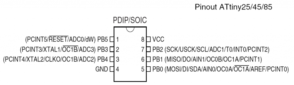
The ATtiny85 microcontroller has six GPIO pins. Each pin can serve multiple functions, which is the reason why the ATTiny85 microchip comes in such a small package. Three pins can be used for programming over ISP because, besides digital and analog I/O, they can be programmed to serve as SCK, MISO, and MOSI. Take a look at the following diagram and check out the various functions of the PB0 – PB5 pins.
Power supply comparison
Microcontroller:
ESP8266 : 3.3V
Arduino UNO: 5V
Arduino Pro Mini: 3.3.V
ATTiny85 : 5V
Batteries:
LiPo: 3.7 – 4.2V
LiFePo4 : 3.2 – 3.6V
OK, the ATTiny85 requires 5V, and the only battery technologies with a decent capacity is LiPo or LiFePo4. To make a long story short, the battery powered and ATTiny controlled night light requires a step up voltage converter to get 5V out of a LiPo 18650 type battery. Fortunately, the small current we draw for the ATTiny and the LEDs keeps even a cheap step up converter within reasonable efficiency levels. There is one thing we still have to keep in mind, though:
I planned for a minimum of four LEDs, mounted in a 90 degrees angle with 2 LEDs each. The maximum current you can draw from an Arduino pin is 40.0 mA, and four LEDs connected to a single pin exceed this limit. We could use two pins, as there are five available on the ATTiny85 package. I came to the conclusion that my circuit would be more flexible if I could deliberately add LEDs to it, up to 8 or even 16. To do that, I needed to add a 74HC595 chip to the circuit. The datasheet refers to the 74HC595 as an „8-bit serial-in, serial or parallel-out shift register with output latches; 3-state.“ In other words, you can use it to control 8 outputs at a time while only taking up a few pins on the ATTiny85 to control it. You can link multiple registers together to extend the number of output pins even more.
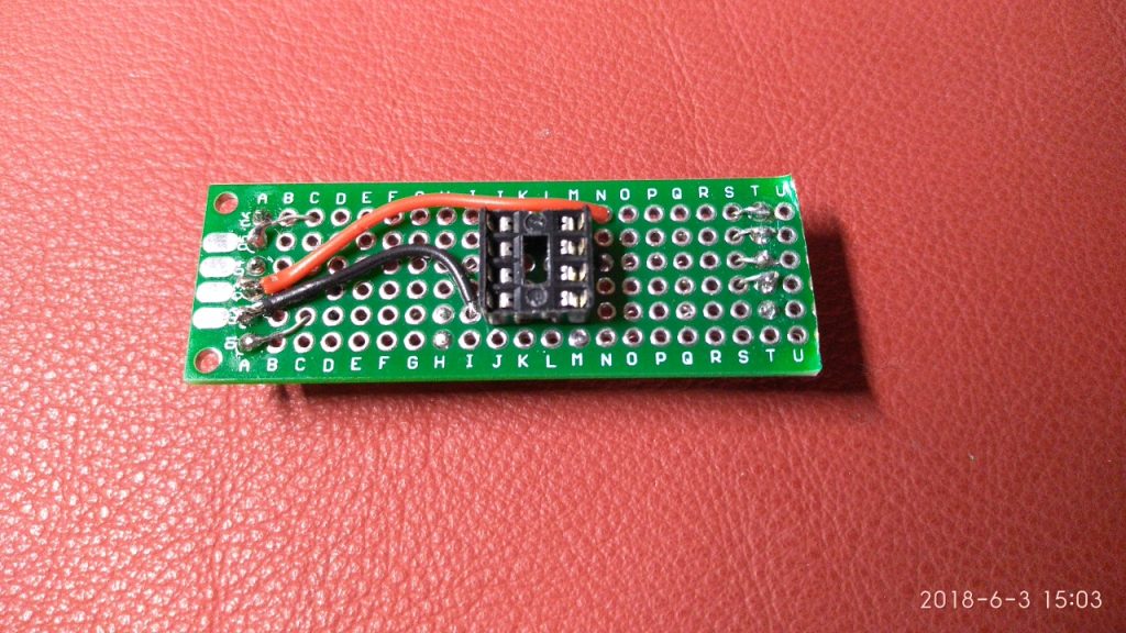
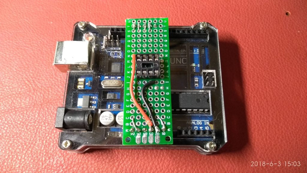
But first things first. We want to program the ATTiny85 microchip with the night light application code. The ATTiny can be programmed over an ISP interface, but to do that, we need a programmer. The Arduino UNO can do that, so after uploading the ATTiny programmer sketch to the UNO, we just need to connect the ATTiny to the UNO’s ISP interface. That’s all what is needed to push the night light code into the ATTiny microchip. Of course you can use a breadboard to setup the programmer’s interface to the ATTiny. A much better solution (if you plan to develop more ATTiny applications), is to make your own Arduino shield. This shield just holds a simple circuit which has a socket for an ATTiny microchip which pins go to the ISP pins D11 – D13 of the UNO (and D10 going to the ATTiny’s RESET pin). The shield plugs onto your UNO and you can conveniently put your ATTiny microchip in and out for programming.
On the Arduino Create Website, there is a good description on how to programm the ATTiny with an Arduino UNO, but don’t forget: Before you can burn a new bootloader on the ATTiny or upload sketches to it, you MUST upload the ArduinoISP programmer sketch onto the UNO and run it!! If you followed the description on the mentioned webpage, you can find it in the Arduino IDE menu under File -> Examples -> ArduinoISP.
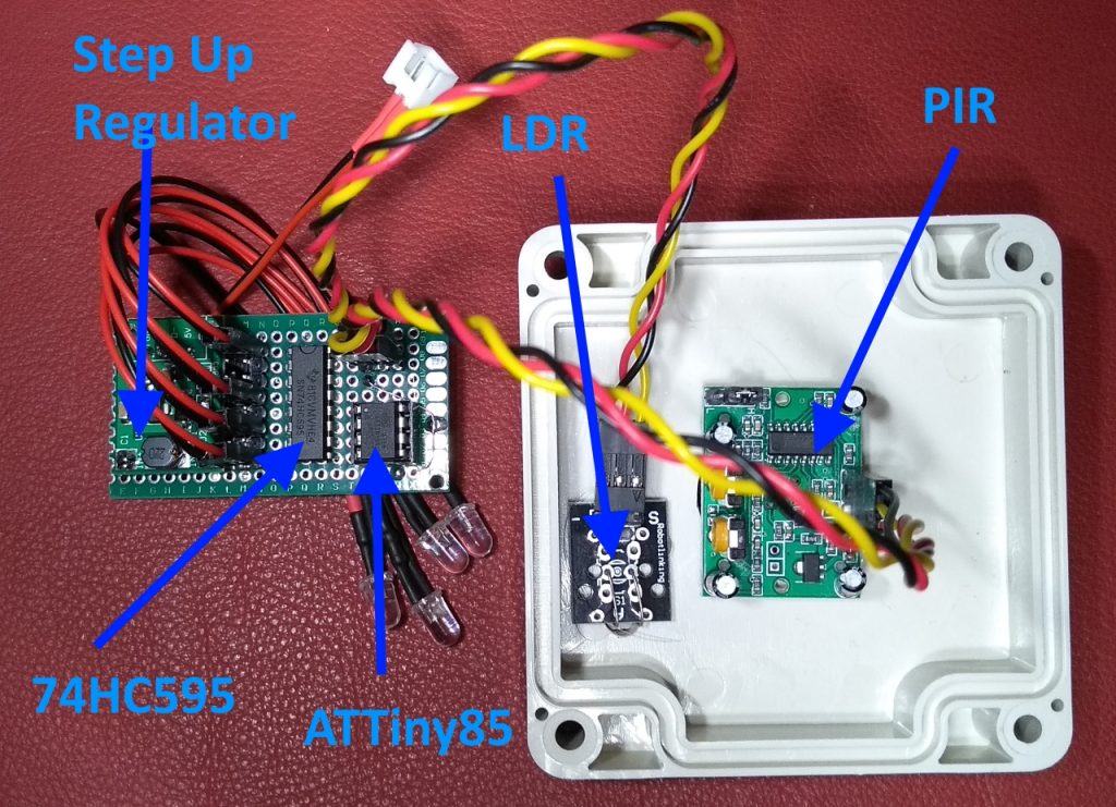
With this out of the way, we can start designing the night stand circuit. The components we need to integrate are:
– ATTiny85
– 74HC595
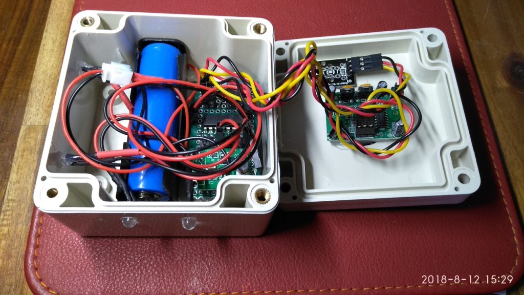
– Lipo 18650 battery
– LDR (Light dependent resistor)
– PIR (IR sensor)
– Step Up voltage converter 5V
– LEDs
ATTiny / 74HC595
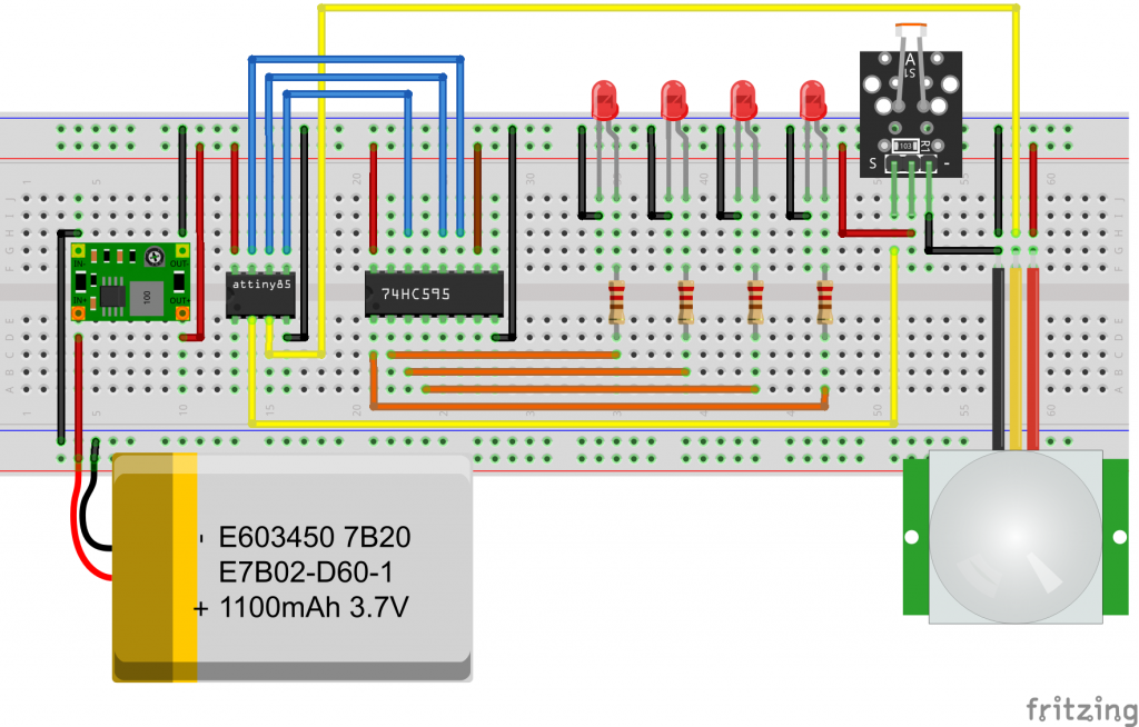
The bulk of connections are between the ATTiny and the 74HC595 shift register. In the following diagram, the connections between the two microchips are shown, omitting the LEDs, which connect to Q0 – Q7:
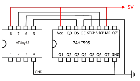
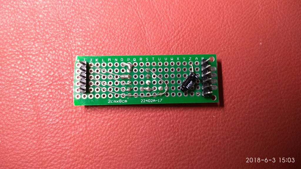
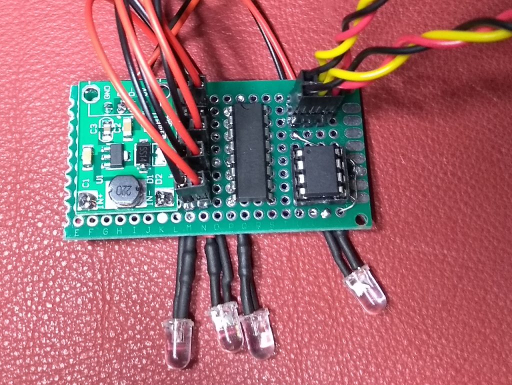
The circuit will run on 5V which comes from the step up voltage converter. For flexibility we will use all eight 74HC595 output pins for LEDs, although the night light will only use four of them. For easy connection of the LEDs, two rows of 8-pin pin headers will be soldered to the board with one row going to GND and each header pin of the second row going to one of the eight output pins of the 74HC595. A separate three-pin header is needed for the connection to the PIR, and another three-pin header for the LDR. After attaching a socket for connecting the LiPo battery the final board should roughly look like this:
Program Code
The night light application code doesn’t contain any surprises. The biggest challenge could be the power down code which puts the ATTiny to sleep if there is no motion detected by the PIR. If the PIR detects motion, it will switch its output signal to HIGH, which triggers an interrupt to the ATTiny85 microchip, which in turn will wake up and switch the LEDs on.
If the LDR detects daylight, it will ignore any motion detection from the PIR, effectively preventing the LEDs from illuminating during the day.
Let’s begin with a few preliminary remarks about the ATTiny85 / 74HC595 interaction. The ATTiny has got 6 GPIO pins (PB0 – PB5) of which we will use three (PB0, PB1, PB2) to control the 74HC595.
| ATTiny | Pin | Pin | 74HC595 | |
| PB0 | 5 | – | 14 | DS |
| PB1 | 6 | – | 12 | SH-CP |
| PB2 | 7 | – | 11 | ST-CP |
There are two control pins on the 74HC595 which we will hard wire to the required signal level:
– OE (Output Enable): is active low. When set to 1 it disables the output and sets pins Q0…Q7 to a high-impedance state.
– MR(Master Reset): is also active low. When set to 1 it clears the contents of the shift register (not the latch).
We are not using either of these pins, so OE must be connected to ground, while MR is connected to VCC.
#include <avr/sleep.h>
#include <avr/interrupt.h>

#define PIRPIN 4
#define LIGHTPIN 3
#define LDR_THRESHOLD 70

//Pin connected to latch pin (ST_CP) of 74HC595
const int latchPin = 2;
//Pin connected to clock pin (SH_CP) of 74HC595
const int clockPin = 1;
//Pin connected to Data in (DS) of 74HC595
const int dataPin = 0;

bool lightOn;

void setup() {
  //set pins to output because they are addressed in the main loop
  pinMode(latchPin, OUTPUT);
  pinMode(dataPin, OUTPUT);
  pinMode(clockPin, OUTPUT);
  pinMode(PIRPIN, INPUT);
  pinMode(LIGHTPIN, INPUT);
  // attachInterrupt(?, wakeUpNow, HIGH); // use interrupt ? (pin ?) and run function

  lightOn = false;
  light(false);
  for (int i = 0; i < 4; i++) {
    delay(250);
    light(true);
    delay(250);
    light(false);
  }
}

void loop() {
  // ** Write to the shift register with the correct bit set high: **
  // registerWrite(bitToSet, HIGH);
  int brightness = 1024 - analogRead(LIGHTPIN);
  if (digitalRead(PIRPIN) == HIGH && brightness < LDR_THRESHOLD) {
    if (lightOn == false) {
      lightOn = true;
      light(true);
    }
  } else {
    if (lightOn == true) {
      light(false);
      lightOn = false;
    }
    sleep();
  }
  delay(50);
}

void light(bool state) {
  byte val = 255;
  if (state == false) val = 0;

  digitalWrite(latchPin, LOW);
  shiftOut(dataPin, clockPin, MSBFIRST, val);
  digitalWrite(latchPin, HIGH);
}

void sleep() {

  GIMSK |= _BV(PCIE);                     // Enable Pin Change Interrupts
  PCMSK |= _BV(PCINT4);                   // Use PB4 as interrupt pin
  ADCSRA &= ~_BV(ADEN);                   // ADC off
  set_sleep_mode(SLEEP_MODE_PWR_DOWN);    // replaces above statement

  sleep_enable();                         // Sets the Sleep Enable bit in the MCUCR Register (SE BIT)
  sei();                                  // Enable interrupts
  sleep_cpu();                            // sleep

  cli();                                  // Disable interrupts
  PCMSK &= ~_BV(PCINT4);                  // Turn off PB4 as interrupt pin
  sleep_disable();                        // Clear SE bit
  ADCSRA |= _BV(ADEN);                    // ADC on

  sei();                                  // Enable interrupts
}

ISR(PCINT0_vect) {
  // This is called when the interrupt occurs, but for this sketch we don't need it
}

// This method sends bits to the shift register:
void registerWrite(int whichPin, int whichState) {
  // the bits you want to send
  byte bitsToSend = 0;

  // turn off the output so the pins don't light up
  // while you're shifting bits:
  digitalWrite(latchPin, LOW);

  // turn on the next highest bit in bitsToSend:
  bitWrite(bitsToSend, whichPin, whichState);

  // shift the bits out:
  shiftOut(dataPin, clockPin, MSBFIRST, bitsToSend);

  // turn on the output so the LEDs can light up:
  digitalWrite(latchPin, HIGH);
}
Some final words to LDR_THRESHOLD. The light dependent resistor (LDR) does not output a constant value, especially not if its getting dark. If the night light behaves erratically or doesn’t work at all, it might be caused by the LDR_THRESHOLD value sitting within the noise. To prevent the LDR prematurely cutting off the LED light because of a spike in the noise, choose a value of 70 or higher. If the value is too high though, light will switch on even if its already sufficiently bright in your room.
My night light’s 16850 battery lasts for around 4 months.